
Hall Effect as it is
In the wake of Nobel Prizes
1. General description
The effect was discovered by Edwin Herbert Hall in 1879 [1]. The Hall effect is the production of a voltage difference across a thin-film (two-dimensional) conductor, transverse to an electric current in the conductor and a magnetic field perpendicular to the current.
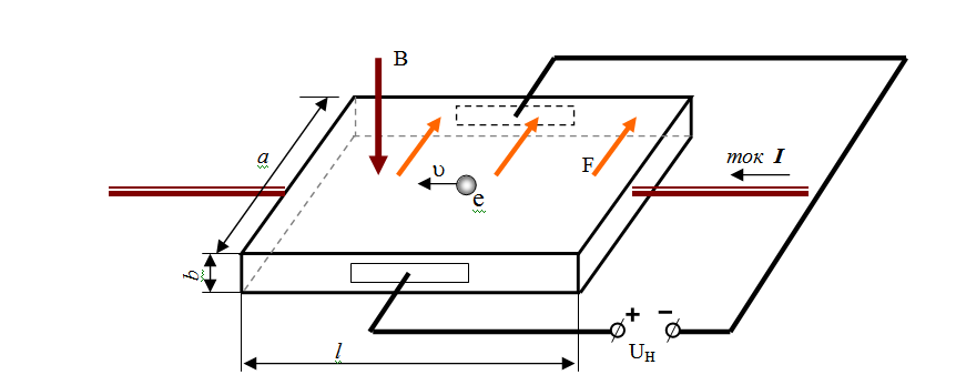
Pic. 1-1.
Scheme of the Hall voltages measurement
Nowadays the generally accepted formula of the effect is the following one.
The current I in the sample is proportional to the speed V and the quantity n=ð1a of moving electrons
I = ð12 aqev(1.1)
Here ð1 is the electron line density (m-1).
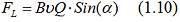
The Lorentz force (the red arrow in the picture) is proportional to the speed as well
F=BVqe (1.2)
Let’s substitute Vqe= I/ð12a from the formula (1.1)
F = IB/ð12a. (1.3).
Hqe = IB/ð12a
Or
H = IB/ð12aqe
Therefore let’s find the Hall tension
Ha = IB/ð12qe=UH (1.4)
The Hall resistance is a ratio UH/IB=Const, i.e.
RH = 1/ð12qe (1.5).
Its numerical value was calculated in the experiments to a high precision RH = 25812,8107 (ohm) [2]. Therefore we find
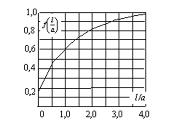
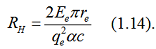
 (1.6)
(1.6)
Thus, the distance between electrons is
z = 1/ð1 =6,431E-08 m (1.7)
According to our data this value is much less.
2. Criticism of existing views.
There are several other solutions of this problem. Thousands of scientists have tried out all the scraps of knowledge in this sphere for 130 years. Among them we can find cyclotron effect and the Fermi level, valency theory and even Landau quantization. But unfortunately physics proper of the phenomenon itself remained untouched.
It must be mentioned that there are a few additional factors and conditions for observing the effect in experiments. They are:
The sample thickness mustn’t exceed a micron
The ratio l/a mustn’t be greater than 5;
Electrodes for measurement of potentials of the Hall resistance must be much lesser than the sample length and they must be located in the middle of the length.
The sample width must be large enough.
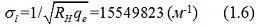
Why and how these factors influenced the effect was omitted so we believe the effect description to be incorrect. Indeed, how is it possible to talk about this very high accuracy of measurement if it is known that the sample length-width ration changes the value of potential [3] several times (Pic. 1.2).
You would probably say that this applies to semiconductors. Let it be. But what would you say about the concentration of free electrons which is proportional to apparent density of material (metal)? It can’t stable as a matter of principle. Consequently, the formula (1.5) is wrong.
So how is the effect proved in experiments?
It’s easy, it is impossible to check the concrete value of concentration. This parameter compensates and masks possible theory deviations.
Pic. 1-2. Dependence of correction function f (l/a) in relation to sample size.
It is logic to suppose that these unmentioned parameters serve as regulators in experiments. It is the source of this strange restriction to sample thickness.
In real physics research of any phenomenon is conducted using principle of particle properties analysis and their behavior instead of selection of different effects [5; 6]. It became possible due to creation of physical models of particles. Such a model was created for an electron as well [7], so we just have to think of any possible consequences which occur with electrons in a magnetic field. If this problem is solved, we won’t just describe the Hall effect, but will be able to answer all the collateral questions.
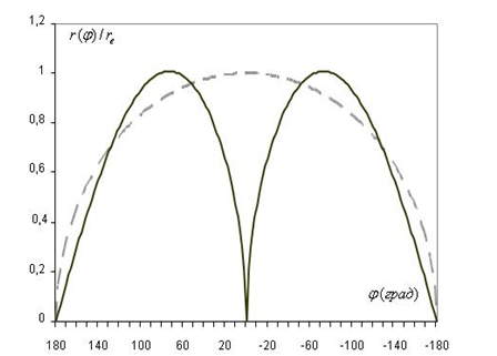
Pic. 1-3 Electron profile in a real physics model.
According to
our electron model, it
mass and energy are contained in a small ball of radius rem
=
2.32034042E-17 m which corresponds to density of energy matter  =
1.74081426*10-19 (kg/m3). Electron sphere is
created by
oscillations of this energy-mass along the generator shown in Pic 1-3.
The
mathematical radius is shown in a dot line.
=
1.74081426*10-19 (kg/m3). Electron sphere is
created by
oscillations of this energy-mass along the generator shown in Pic 1-3.
The
mathematical radius is shown in a dot line.
Due to the energy-mass oscillations along this colourful curve and its rotation about the X-axis all the characteristic properties of an electron appear. Harmonic oscillations of energy-mass have such a high frequency w1 = c/re that interacting electrons don’t manage move over a period of this frequency T1 = 5.90596E-23 s. Orbital frequency is much lesser w0 = …. and the period T0 = 8.0933E-21 allows reactive forces to intrude upon leisure of their ‘vis-à-vis’.
The consequence of these properties is the formation of an unwinding spiral as a ‘band’ of high energy density in the space around an electron. And if a remote observer registers these pressure waves P= E/V with a period T0 and wavelength
 =cT0
=2,42631E-12m(1.8).
=cT0
=2,42631E-12m(1.8).
There is no need to explain that it is the de Broglie wave and it isn’t formed due to particles mass. It is the way how naturally effects become apparent in real physics. The Hall effects is to be explained like that.
We need to pay attention to two electron properties for solution of our task.
The first property is well-know: a moving electron orients its axis of symmetry relative to the speed vector. Frankly speaking, it is not this property that is well-known, but its consequence: a vortex magnetic field is formed around a moving electron. This is a property of energy-mass orbital rotation and orientation is achieved due to asymmetry of electric acceleration forces of energy-mass in half waves of oscillations.
The second property became apparent only from our electron model: a magnetic field affects to the maximum in electron equator plane, i.e. perpendicular to the symmetry axis. The consequence is an electron accelerates along the force vector and as a result changes the advantageous orientation reducing the efficiency of magnetic force. As a result, the compromise is reached if the symmetry axis is inclined at an angle 45° to the displacement vector.
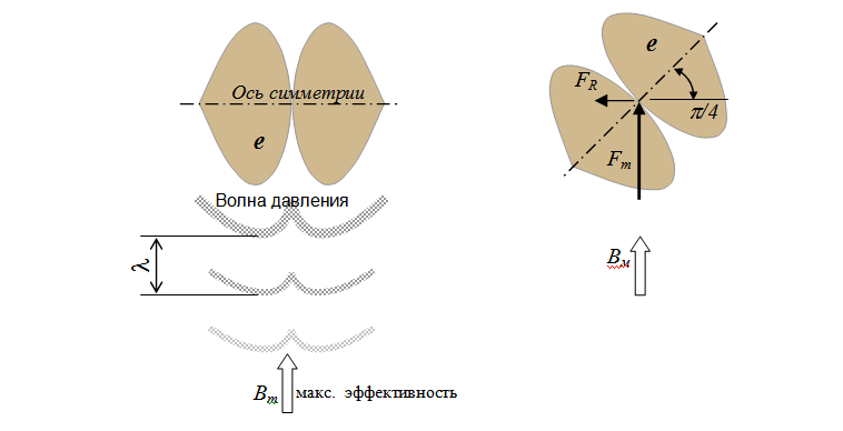
Pic. 1-4 Electron orientation in a magnetic field.
In Pic. 1-4 you can see an electron leaving the maximum action of magnetic field for the compromise orientation. According to the laws of classic mechanics magnetic force Fm affecting inclined surface creates lateral reaction force FR. A hard pressure wave acts as inclined surface.
If you look closer at the right picture, you will notice that interaction of the displacement vector and the ‘inclined surface’ will not change if an electron is rotated around the force line of Fm. Reactive force FR rotates in the same way remaining in the same plane with the electron symmetry axis. It means that statically even orientation of electrons affected by the magnetic field make electrons scatter from the centre and yield to force Fm.
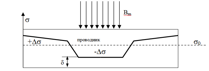
Pic. 1-5 Change of electron concentration in metals under the influence of local magnetic field.
But if electrons are forcedly oriented in one direction in the horizontal plane (to create current), it will turn out that reactive force FR of all the electrons is perpendicular both to the current and the magnetic induction. This fact is well known as well, this force is called the Ampere force.
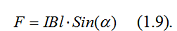
How is it different from the Lorentz force?
By definition it is the same force, consequently, IL =VQ or I = VQ/l. The sense remains for a single electron as well I = Vqe / z. So the Hall effect can be observed in the parameters of a single electron.
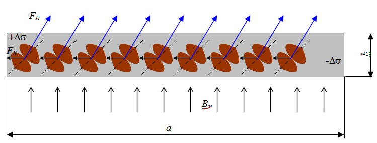
Pic. 1-6. Shift of electrons to the lateral surface of the conductor by magnetic force FR.
If we consider the processes in a thin-film conductor, we will find out that:
·
The zone (- ) in
the conductor thickness in Pic 1-5 disappears
due to small distance ð˂2z;
) in
the conductor thickness in Pic 1-5 disappears
due to small distance ð˂2z;
·
The zones (-)
and (+) appear at the lateral surfaces of the
conductor (Pic. 1-6).
·
Electric
force FE directed along the lateral
surfaces of the conductor doesn’t change the electron orientation
in the
picture plane, but only ‘inclines’ it along the conductor
length
(β angle in
Pic. 1-7).
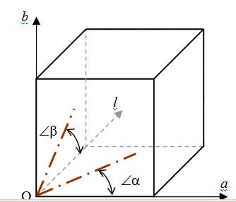
Pic. 1-7. Orientation of the symmetry axis of an electron by magnetic field (α-angle) and electric one (β-angle).
As the α-angle is constant and equal to π/4, it seems that electron pressure on the lateral surface bOl remains constant with any current as well. It is the compression of electron column that allows to increase concentration of electrons (Pic. 1-6), i.e. increment of potential
However, let’s go back to Picture 1-5 showing that if there is no current, any compression doesn’t create potential difference. Indeed, there is the increment (+Δð), but it is equal in all directions. Consequently, magnetic induction just creates potency of potential increment, and it is realized by means of current. To be more exact, by means of electron orientation proportional to the current.
So the potential difference (The Hall voltage UH) is a projection of an electron potential vector. The current that we have chosen selects an angle of projection of electron current on the conductor plane. It gives us full scope because electron parameters are known to us and we can search for the primary Hall effect not in voltage UH, but in resistance RH from the electron model. The Hall voltage can be calculated
UH = I*RH (1.12).
Let’s calculate electron current knowing orbital speed of energy-mass
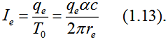
Electron potential is known φe=Ee/qe so we can immediately find electron resistance
The numerical value of the Hall resistance can be now calculated very accurately RH = 25812.8141043784 (ohm)1. (Accuracy of the last 4 figures is relative)
1. Explanation of contributing factors and conditions.
The reader may have a question if the ratio RH = φe/ie remains the same for a set of electrons. There are psychological grounds for it as a current is formed by all the electrons of a conductor, and potential is created only across the width of a conductor. It must be taken into account that only n = a/z electrons of section form the current.
And what happens with transverse compression of the structure? Here a domino effect is created: when the front electrons bear against the conductor edge, the back ones push them. All n = a/z electrons are slowed down by turns and as a result, the force of lateral compression increases too and in the same way as the current
FΣ=FRa/z(1.15).
As a result, the ratio of the Hall voltage to the current in a sample DOESN’T DEPEND on size and material of the conductor.
The two most important facts are:
· The physical reason for usage of superfine flat conductor is finally found. If the thickness increases, several electron layers will participate in current creation and the Hall resistance won’t change.
· The Hall resistance doesn’t depend on electron concentration so the existing rule of its calculation (1.5) is wrong. But the independence of resistance from conductor material has been proved.
As for conductor width and organization of a side electrode, the point is the following:
The force (1.15) is great. It makes electrons press themselves to the metal edge. Microroughnesses are filled by electrons thus creating ‘sacks’ that don’t participate in conduction. That is why a significant reduction in current occurs when a current circuit is fed by a low-resistance source. In order to reduce this effect rather large width a is chosen which allows to increase the total force (1.15).
In Pic 1-8 you can see the summarized effect of electric and magnetic forces on electrons.
Magnetic
field action area
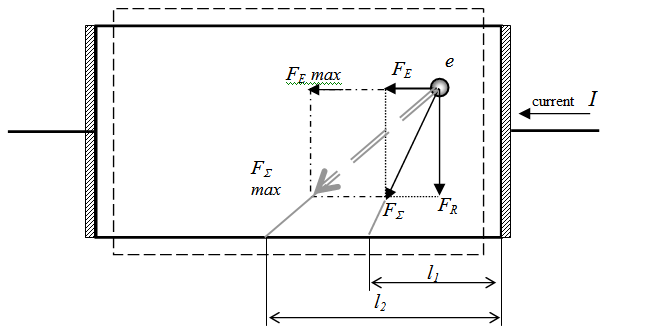
Pic. 1-8. The scheme of end effect in a conductor.
One can see that summarized force … creates the effect over some distance l1 from the conductor end. Thus, if the current (magnetic induction) value is changed, the maximum value of this parameter l2 can be specified. The potential on the electrode side grows along the length l1 from the end (Pic 1-2) and it can’t be equalized with a common electrode. So as a rule the electrical lead is made in the middle of length allowing to change the current direction as well.
As a significant part of conductor length is used inefficiently, one has to increase conductor length in a constructive way. It is especially important in measuring sensors when great multiplicity of current change and magnetic induction must be achieved. It leads to a constructive limitation l≥5a.
Conclusion:
The existing description of the Hall effect is wrong.
Links:
1. Klitzing K. Kvantovii effect Holla [Quantum Hall Effect]. UFN, 1986. Vol. 150, issue 1.
2. GOST 8.417-2002. Gosudarstvennaya sistema obespecheniya edinstva izmerenii [State System for Ensuring Uniform Measurement].
3. Effekt Holla [Hall Effect]. http://foez.narod.ru/42.htm
4. Drude P., Zur Elektronentheorie der Metalle. – Ann. Phys., 1900.
5. Rudnev A. D. Novaya kontseptsiya fiziki [New Physics Conception]. http://www.sciteclibrary.ru/rus/catalog/pages/6910.html
6. Rudnev A. D. Posle veka illuyzii [After Century of Illusions]. http://314159.ru/rudnev/rudnev3.htm
7. Rudnev A. D. Elektron [Electron]. http://phisics-anime.narod.ru/anime.html