New
understanding of the skin-effect
A.D.
Rudnev
The essence of the
skin-effect
in the
fact that the conductivity of the conductor isn't uniform
on
cross-section and is defined,
in practice, as a thin surface layer of
the
section.
This is perhaps
the
oldest, most famous of
electrical
effects. It studied
many times,
but
only in
the sense of quantitative
expressions
for approximated
description
[1].
To its
credit, science
didn't assignedd to this effect hypothetical
mechanism
of its
creation, despite the presence of
multiple
versions [2] of it. We
assume the
effect as
a benign
tumor,
that not leading to the
disease of other
"organs".
The study
of the
effect is
needed more
for
ourselves
for demonstration
the
abilities of real physics.
Such
an investigation must be preceded by
a
summarizing of features of
the
toolkit. The main tool
will be
our model of the electron
[3],
as well
as the real physics
of
magnetism.
We would
emphasize one of the properties of
an
electron, the ability
to orient
the axis
of symmetry (Fig. 1)
along the
line of motion.
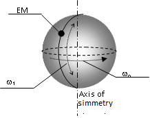
Fig.
1. Scheme of inner cinematics of electron
Energy-mass
(EM) performs
central-angle
oscillation
"through the meridians" an imaginary
sphere
with
frequency ω1 =
c
/ re.
An
imaginary sphere,
and with
it
-axis
of
symmetry - make
reactive
opposite
vibrations
that
creates
the effect of spherically
symmetric
field of energy in space.
Simultaneously,
the EM
does
orbital
rotation with angular frequency
ω
0
=
αω1, i.e.
with a
constant linear velocity υ
0 =
αc.
The
action of an external electric fieldcauses
the
electron to orient
the axis
of symmetry along the line
of
tension. at the same timeposition of the plane
of the
orbit is also
stabilizing,
therefore
in the
space formsdirected
vortex of
magnetic field.
This is
due to the CoulombEM
interaction
with sptial
charges [6].
In the
motion electron also
orients
its axis
of
symmetry along the line
of motion
-
thanks to
the same interaction.
In this
case, the
magnetic field is proportional to
speed.
To
analyze the
physics
of the processes in this
effect,
we need to consider the action of vortex
magnetic
field on
the electrons,
that create this
field.
In modernconception there is no bridge
linking
the magnetic moment
with
a
structureless electron.
In our
scheme (Fig. 1)
an
electron at rest has the property of
the
oscillationsНам
На
рис.2 изображен проводник, в котором протекает ток,
первоначально
предполагаемый
нами как равномерный по сечению.
of
orbit
on
±
π / 2,
making the projection of
the
magnetic moment (MM)
on an arbitrary
plane
equal to
zero.
The
narrowing of the angle of
oscillation,
which occurs at the symmetry axis
orientation,
violates the condition that the
MM is
zero
at the
conductor and around and creates a
magnetic
field
vortex
This means that the
electron
can not be
indifferent
to the
magnetic field and that own magnetic field
also
affects the trajectory
of the
electrons. Remain to us to take into account the full range
of
possible events simultaneously.
Figure 2
shows a
conductor
in which current flows
initially assumed
as a
uniform by section.
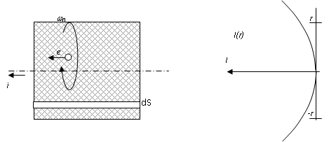
Fig. 2. Vortex
magnetic field of conductor with current.
Since
the current density is assumed constant
γ
= Const, then
the total
current in conductor
section
I
=
γS
(
1)
выражается
диаграммой на рис.2 (справа).
Соответственно,
в теле проводника формируется вихревое
магнитное поле с
напряженностью
expressed by
the
diagram in Figure 2 (right).
Accordingly, in the body
of the
conductor is formed a rotational
magnetic
field with tension
( 2).
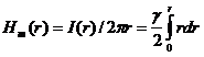
However, this is
only a
description of the magnetic
field
generated by current
covered by
the
section dS in
the
section of the conductor (Fig.
2) induction for
each
elementary ring formed
in the
covered
circle
is
external. The
Lorentz force
FN,
defined
by the
rule of the left hand,
is directed radially to
the center
of
conductor. And there comes
the most
subtle point related
to the
behaviorof electrons.
First,
the
volume density of free charges
σ
(FC)
becomes heterogeneous,
higher
in the
center of conductor.
Second,
the path
of the
electrons became curvilinear,along
withelectric
tension
in the
conductor, there is operation of magnetic induction.
He = U
/ L
(3)
But
the
geometric combination of forces
shows
only
the
deviation of velocity
of an
electron from the vector of tension of
electric field.
Fig.
3. Compression of the structure of free electrons by Lorentz force.
And
as
what is
reaction of electron -
it
should
change
the orientation of the axis of symmetry
by the new
velocity
vector?
It is
easy
to see
that
there is
a single possibility to
compromise
- movement
of romb
formed by
the
electric and magnetic forces (Fig.
3).
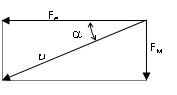
Fig.
4. The diagram of vector forces, operating on electrons in the
conductor with current.
The
axis of
symmetry
of the
electron deviates from
the
velocity vector at an angle
α.
Since
induction
-is
the result of collective
interaction
of the electrons,
the radialmagnetic force
is
greater than the electrical
force
acting on
the individual electron.
That is,
the
radial displacement of electrons
significantly
reduces
the value of the current.
A measure
of replacement
energy
of the
electrons movement is
the work
of compressionthe structure.
Ранее
нами определено [8], что в воздушной среде расстояние
между свободными
We have previously
determined
[8],
that in the air
distance
between
the free electrons 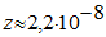 ,
and for specific medium it
can be determined with use of the
ratio
of bulk
densities.
For
example, for copper
,
and for specific medium it
can be determined with use of the
ratio
of bulk
densities.
For
example, for copper
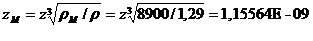
(
4).
According
to the force of Lorentz, compressing the flow of electrons
Fт
=
Вmυqe
(
5)
-it
is
impossible to calculate without knowing the
velocity
of the electrons.
Modern
physics does not know number of free electrons
in the
conductor, and
the speed
of their
movement. the flow of electrons
Традиционным
способом можно вычислить постоянный ток в
проводнике заданного
We
can calculate the
direct
current of given section of conductor
with
given tensity in the traditional way/
For
example,
in a
copper conductor
with
diameter of 0.2 mm
(at a voltage of
0.1 V
at
1 m long),
a current
flows with a value of 0,1848
А.
Lets
calculate.
The
volume of conductor v = 3,14159E - 08 m .
The
atomic mass of copper ma = 1,05E - 25 kg,
the
quantityof copper atoms х = M / ma = ρv / ma = 2,66287E + 21
,
the
volume of copper atom va
= 8,78453E - 30 m^3,
the
free volume in conductor
v0
= v
− хva
= 8,02383E - 09 m^3,
the
number of free electrons in it
n = v0
/ z М^3 = 5,19893E + 18
total
moving charge
Q
= nqe
= 8,32E - 01 C.
(
6).
By the way, we obtain
a useful
constant -
the
specific charge of the masses
θ
= Q / ρv = 2975,049656 (Кул/кг)
(
7).
В
таком случае, скорость движения электронов (для выбранного
примера) определится
величиной
In this case,
the
velocity of the electrons (for
selected
example)
will be determined by value
υ
= Iz / Q = 2,57E - 10 (m/s)
( 8).
Стартовое
включение проводника вызывает пару
взаимно-перпендикулярных сил:
The starting
turning on
of the
conductor causing
a pair of
mutually
perpendicular forces:
axial
F=qEVe
and radial - force of Lorentz. Lets find the radial shift of electrons
in conductor
For this we will define
the
initial value of the Coulomb force of interaction of free
electrons
of the structure
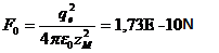
( 9).
Comparing
it
with
the
electric force F=qEVe=
1,60E - 20 N, заключаем, что она
не
способна изменять решетку пространственных свободных
электронов. Магнитная
conclude
that it can not
change the
spatial
lattice
of free
electrons. Magnetic force, whose graph
is
similar to the current function
(Fig.
2),
even
smaller. But there is a
nuance:each electron
producesits
strength
of interaction with the magnetic field,
so towards the
center
forces are added.
Deformation
structures
are different
radial
guide and
they are
also summarized.
But, the
summation
is
in the
opposite direction.
Деформацию
ячеек структуры на радиусе r оценим относительно
силы кулоновского
сжатия
Deformation of the
cell
structure
at a
radius r
we will
calculate relative to the strength
of the
Coulomb compression
(
10).
Just
substitute
not the
value of magnetic force
(5),
but the sum of forces acting on section from the
surface
of the conductor to
the
current radius
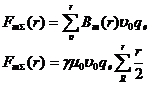
Воспользовавшись
линейностью зависимости силы от радиуса,
введем среднее значение
силы
на заданном отрезке и заменим суммирование умножением
Using the
linear
dependence of force
on the
radius,
we introduce the mean value of force
on a given
segment
and
replace the summation
by
multiplying
 (
11)
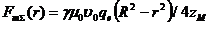
(
11)
D =
γµ0υ0qe
/4zM
= 6,43E - 32 ( N / m^ 2 ) ,
Substituting
the values of
the
permanent members obtain a simple
expression
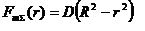
( 12).
On the
fig 5 shown the graphs for this equation
a)
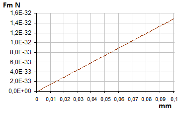
b)
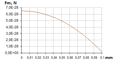
Fig.5. Dependence of Lorentz force on radius of conductor (а) and sum
of radial forces (b).
Like
a column
of liquid,
the total
force rises
the deformation
while approaches to the center of conductor(4) of the electrons structure.
Not only total
deformation
of column,
but also particular values have
essentially
nonlinear dependence
on the
radius (Fig. 6).
a)
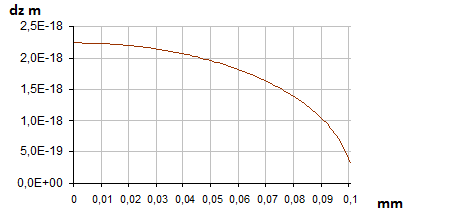
b)
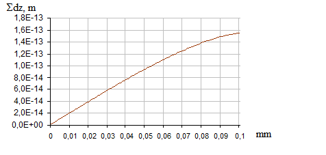
Fig. 6 Dependence of the
deformation
of
structure of
the
electrons on radius
of
the conductor (a)
and total deformation of
"beam"
of electrons
(b).
A characteristic
feature
of the functions
is that
the total
force is maximal near the
center
section,
and the total
deformation,
on the
periphery. So energy
of
deformation (compression
work)
has pronounced
extremum(Fig. 7).
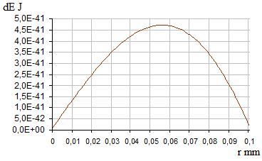
Fig.
7. Nature of work change of structure compression along the length of
the
electron beam.
Here
we saw the work of compression of single electrons beam.
dE(r
) = FmΣ∑dz
( 13).
It
is clear that
in the
section of the conductor the number of such
rays is equal to
πR
/ z, and the number
of
electronic layers (sections)
along the
length of the conductor
is equal
to L / z,
ie, the scale of
the curve
in
Figure
7 should
be increased by πRL / z^2 that in our
example
is equal to
2,35E + 14 .
Summary diagram
of the
energy costs on
electrons
structure compression
is shown
in Figure 8
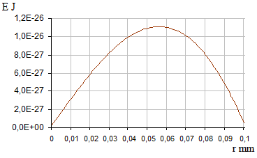
Fig.
8. Total energy costs diagram
Lets recall that the
primary
driving
force was the force
created by
the
tension (3)
of the
electric field. The movement
of
electrons created a current,
and it created the
magnetic field.
So
that the
effect of compressing
the
structure of electrons occurs
in the
final due to
inhibition
of the electrons,
ie,
by
reducing the current. If we will summarize the
energy
consumption E
Σ
(r), we
would obtain
the maximal
work necessary
to recieve DC
in
conductor. In this example this value is Е
Σ = 7,31E - 25 J. How to compare the energy with electric
power? We need parameter of time. But
this parameter need to affect only real processes - movement
of electrons. So if the power of electric loss UI
= 1,85E - 02Wt we need to consider only the power of movement
N =
nFυ = 2,14E - 11 Wt
(14).
Everything else - is
the
energy loss by the interaction of electrons
with atoms,
and this is tthe reason why uniform motion
of
electrons does not go
uniformly
accelerated.
Interesting
- by how many times the total loss of energy is greater than the
effective loss, it turned out that by
8,65 E +08
times.
So, even
with such low efficiency it seems to us, that there is enough time
τ
= E Σ / N = 3,42E - 14c
(
15)
to
complete the transition processes. But no, we should emphasize
the nature of structure compression process: the pressure
comes from the surface of
the conductor to the center, and the deformation grows in the opposite direction. Consequently,
for each coordinate of
elementary ring,
the cycle of "deformation - the force appearance"
and vice versa is repeated. That
is, the deformation
occurrs alternately, causing the compression time
to be stretched. Assumed mean value of
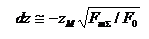
coordinate
r = R/2
we find the average number of cycles x
= R / 2zm
деформаций
в одной координате. Тогда полный опрос
электронного «луча» произойдет за
время
deformations in one
coordinate. Then, complete
progress of electrons
"beam" over all the cycles will occur in time
 (16)
(16)
In our examle R = 0,0001 м х = 1,87 E + 09
and time Т =
хτ = 6,40E - 05s means that after 64 ms after
the conductor is
turned on, current in it will become uniform over the cross section.
The frequency dependence of the
process is in simple stabilization
of the operating point - in the extremum of the curve in Figure 8. In this case the amplitude value of the maximum in the graph will fall in proportion of the period
to parameter Т = х τ .
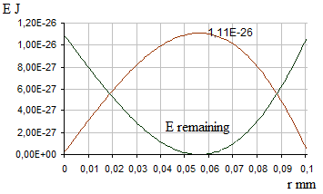
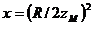
Fig.
9. Recieving graph «remaining energy».
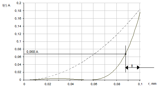
Fig.10. Diagram of steady-state current (dashed
line) and limiting transitional process.
Чтобы
перейти к закономерности распределения тока по сечению
проводника,
необходимо
отметить следующее: если работа магнитных сил
происходит за счет тока,
он не
может стать нулевым, т.к. иначе исчезнет и магнитное
поле. Словом, существование
магнитного
поля во время установления режима тока должно
происходить в паритете
энергии.
Иначе говоря, максимум энергии на диаграмме рис.8,
соответствует максимуму
возможностей
системы в целом. Это значит, что энергию
полезного тока можно
отсчитывать
от этого пика, как от предела вычитанием энергии
сжатия структуры (рис.9).
To proceed to low of current
distribution over the cross
section of the conductor, should be noted following: if
the work of the magnetic forces is due to the current, this current cannot be zero, since otherwise the magnetic field would
dessapear as well. In
short, the existence of magnetic
field during the current mode
shoud be set with balance of energy. In other words,
the maximum energy in Figure 8, corresponds to the
maximum capacity of the system as a whole. This means that
the energy efficiency
of current can be measured from this peak, as from the limit by subtracting the compression energy of structure
(Figure 9).
And since it is clear that
100 percent expression of elementary ring cross section energy capacity is its
ability to provide current γπr^2
, so we correlate remaining energy Е =
1,11Е − 26 J with the nominal value of constant current I (r
) .
Consequently, the transition to the current I (r) of transition
process is sufficient to normalize
the steady current I (r ) =
γπr^2 with similarity coefficient k = E
remaining / E max
I (r )
= γπr^ 2E remaining (r ) / E max
(17).
Diagram of limiting transition process current in the
conductor is shown in Fig.
10. The width of the δ zone of conductivity,
defined as the decreasing in current density by a factor e,
covers about 65% of the
total current of the conductor. The process of transition by the
limiting mode is known in science as "self-inductance
effect of the conductor."
The perfect equality
of the magnetic energy and
the energy corresponding to
the electrical conductivity,
in practice violated.
This occurs due to diamagnetism or paramagnetism of the material of the conductor.
In the first case, the
magnetic properties are
weakened, causing compression of
the structure to be smaller.
In the second case, all on the contrary. And
the result of the manifestation of these
properties is illustrated by
the diagrams in Fig.
11.
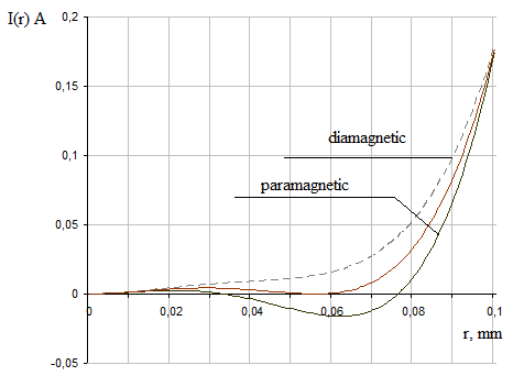
Рис.
11. Influence of diamagnetism and paramagnetism of materials on
limiting mode.
As
can be seen from the figure, it is demonstrated here another
new feature of the
phenomenon - negative
current of paramagnetics in some elementary rings of cross
section near the 0.6 radius of the conductor.Manifestation
of the skin effect on
alternating current does not reach the limit curve. Working
curve with
increasing the frequency shifts from the dashed line in Figure 10
to the dashed line in Figure 11. Therefore, in practice it
has a form characteristic for
the limit diamagnetic mode.
Bibliography:
1.G. Ebert "Kratkii spravochnik po
fizike" (Quick Reference Guide to Physics).
M, F-M, 1963, p.444
2. T.I. Trofimova "Kurs fiziki" (physics
Course). M. The high school, 1997
3. A.D. Rudnev The new conception of
physics.
http://www.sciteclibrary.ru/rus/catalog/pages/6910.html
